EVERYONE EVERYWHERE can be empowered to independently purify unsafe water into distilled, safe water to drink using locally available materials and energy sources. Everyone Everywhere Purifiers are fully scale able from individuals to households to entire cities.
ANY COMBINATION OF ANY SOURCES OF HEAT (Herein “heat” is used as synonymous with “thermal energy”.) can be used to power Everyone Everywhere Purfiers: solar power; waste heat from stoves, engines, furnaces, etc.; burned fuels; geothermal heat; heat from compost piles, etc. etc. etc.
MOST PRACTICAL heat source is exhaust heat from an engine, furnace, stove, kiln, etc. Simply use the Everyone Everywhere Purifier like an exhaust hose extension.
VERY PRACTICAL heat source is biomass such as straw, wood, dung, empty corn cobs, seeds, dry leaves, cloth, paper, alcohol, bees wax, etc etc etc.
LESS PRACTICAL is fossil fuels such as oil, methane, propane, paraffin wax.
LEAST PRACTICAL heat source is Solar Energy. While a Everyone Everywhere Purifier will work fine with solar power alone, it can only work with as much power as the Sun will provide. Even at the equator, on a cloudless day, a 1 square meter Everyone Everywhere Purifier at 100% efficiency could only purify 15 liters per day.
Formula: (solar constant at Equator * evaporation area * 12 hours/day * 3600sec/hour *
average sine of 1º through 90º ie rising and setting sun) / enthalpy of water = maximum liters/day
Calculation: (0.00137 mJ/sec/m2 * 1 m2 * 12 hours/day * 3,600 sec/hour *
0.642159 average sin) / 2.454 mJ/liter = maximum 15 l/day purified.
Burning biomass is much more practical and just as sustainable as direct solar power. Biomass is, after all, concentrated solar power. The Sun will shine. Plants will grow. Then plants will rot, putting methane into the atmosphere UNLESS we harvest plants and capture their methane production.
HOW THEY WORK: the guiding principle for Everyone Everywhere Purifiers is the universal one for distillation, ie evaporate and re-condense water. However, Everyone Everywhere Purifiers do not distill water by directly heating a big pot of unsafe water and cooling the steam. Instead, captured air is repeatedly heated, allowed to collect evaporated water, cooled to release the water, then heated again to restart the cycle. Capillary action/wicking is used to partially purify and spread out water for the air to absorb.
ADVANTAGES of EVERYONE EVERYWHERE PURIFIERS
1. Everyone Everywhere could build a working purifier using scraps from a garbage pile
2. Publishing this writing should make the idea not patent able.
3. Uses any combination of heat sources
4. Scale able from single person to city
5. Can use locally available materials (beware of temperature maximums)
6. Install able on boats and vehicles
7. Quick, low cost cleaning process to undo fouling by salt residue etc
8. Can be operated by non-engineers
9. Simple, affordable, reliable
10. Do NOT need moving parts
11. Do NOT need chemicals
12. Do NOT need filters
13. Do NOT need electronics
My purpose in publishing this paper is to make this idea not patent able.
Thus everyone everywhere can design and build their own versions.
My research has been done primarily on the internet, so checking my research and checking my math are both worthwhile. Everything I have written here is to the best of my knowledge and belief.
Phil
joyfulcatholics@protonmail.com
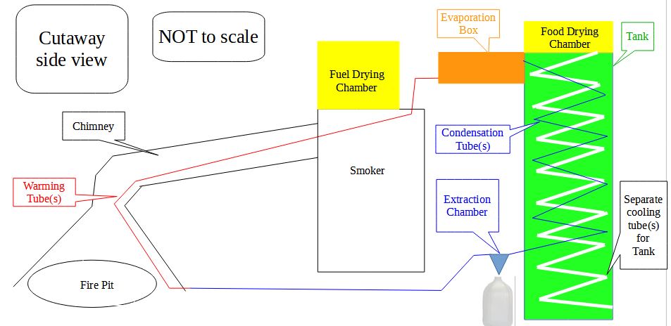
This example was designed for a household that already had a fire pit and a smoker.
1st Step-Planning
SUB-SYSTEMS
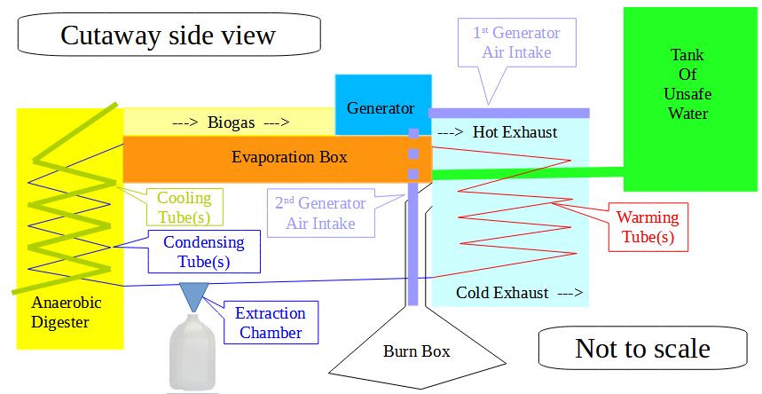
Working Air: circulates repeatedly from Warming Tube to Evaporation Box to Condensing Tube to Extraction Chamber to Warming Tube (start over)
Distilled Water: drips from Condensing Tube to Collection Chamber and out.
Unsafe water: flows from Tank to Evaporation Box
Smoke: rises from Burn Box to Chimney Chamber where it drifts down as it cools.
Cooling Air: is ambient air that rises through Cooling Tube(s) to Food Drying Chamber.
Drying Chambers: use excess heat to dry their contents.
SUGGESTED DESIGN (Detailed in following pages)

NOTES
• The sizes and arrangements of the components do NOT have to follow the drawings. As long as warming air is allowed to rise and cooling air is allowed to fall, the specific design is flexible.
• Within the limits of maximum temperature tolerances, any water tight materials can be used.
• No insulation is shown in this design, however, insulation will increase efficiency.
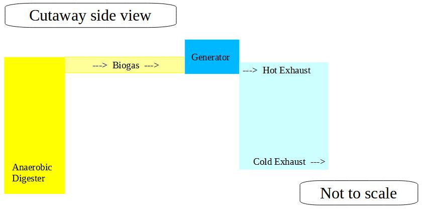
• The included design uses heat content of exhaust from the generator and/or smoke from a fire. However, any flow of heat can be used.
OPERATING TEMPERATURE
With this same design, higher operating temperatures will power faster purification volumes.
Operating Temp of 100ºC can purify about 66 liters per day.
Operating Temp of 200ºC can purify about 154 liters per day.
Operating Temp of 300ºC can purify about 242 liters per day.
Operating Temp of 400ºC can purify about 330 liters per day.
Operating Temp of 500ºC can purify about 418 liters per day.
Operating Temp of 600ºC can purify about 506 liters per day.
Operating Temp of 700ºC can purify about 594 liters per day.
Operating Temp of 800ºC can purify about 704 liters per day.
FLAME TEMPERATURES
Wood Type Flame Temperature
Beech 950°C/1742°F
Birch 816°C/1500.8°F
Douglas fir 350°C/662°F
Oak 900°C/1652°F
Pine 500ºC/930ºF
Radiata pine 349°C/660.2°F
Redwood 364°C/687.2°F
Spruce 620°C/1148°F
Victorian ash 311°C/591.8°F
Western Red Cedar 354°C/669.2°F
Notice: per kilogram, different types of wood will give the same total heat, 3600 Kcal/kg
Fuel Type  Flame Temperature
Biogas (50% methane) 975 ºC
corn cobs  1100 ºC
cow dung (dried)  640 ºC
ethanol  1920 ºC
gasoline  2138 ºC
hydrogen  2210 ºC
natural gas (methane) 1950 ºC
propane  1980 ºC
straw  250 ºC
Auto exhaust is typically 200ºC (400ºF).
Diesel exhaust is typically 280ºC (540ºF).
2.5 kW generator exhaust is typically 315ºC (600ºF).
As long as the Wicks are saturated with water, their temperature cannot rise over the boiling point of water. However, other parts could be ruined by excess heat and if the Wicks go dry, substantial damage could also be done to the Wicks and Evaporation Box. In fact, some room should be left between the chosen Operating Temperature and the melting temperatures of the materials used.
Metals
660°C (1220°F) is the maximum for aluminum
1375 – 1530°C (2500-2785°F) are the maximums for various stainless steels
Sample Wicking material options
200ºC (392°F) is the maximum for cotton
268ºC (514°F) is the maximum for nylon
800ºC (1,472°F) is the maximum for stainless steel wool
2nd Step-Anaerobic Digester
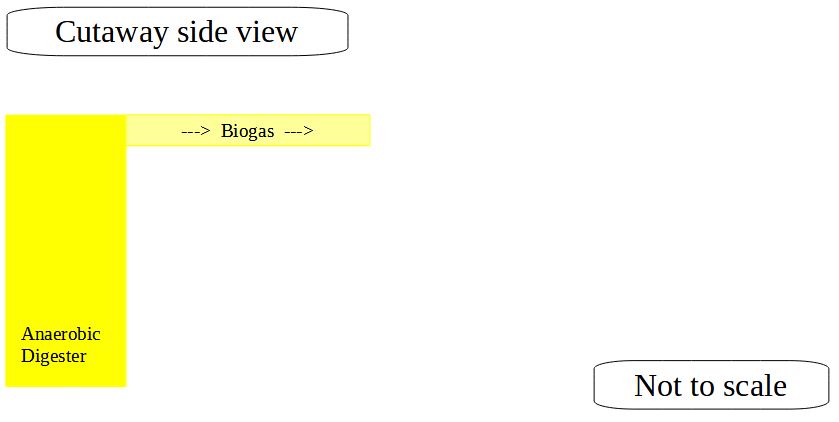
 1. Need: a water tight container, some grass, some water, and some manure. Combine them, wait a week, and methane will be produced.
 2. Best thermophilic (digestion) temperature range is 50 to 57 ºC (122 to 135ºF)
 3. Leftovers from bio-digestion are liquid effluent and semi solid digestate. Both are good fertilizers.
 4. Some URLs to get your research started
    1. https://www.epa.gov/agstar/how-does-anaerobic-digestion-work (gov explanation)
    2. https://americanbiogascouncil.org/resources/what-is-anaerobic-digestion/ (trade group explanation)
    3. videos
       1. https://www.youtube.com/watch?v=IGPEP9EZU3Y  (academic explanation)
       2. https://www.youtube.com/watch?v=x95d_cCDOL0  (DIY in barrels)
       3. https://www.youtube.com/watch?v=TA0l2EC77w8  (DIY in barrels)
       4. https://www.youtube.com/watch?v=OhScJBxLDSA  (DIY in garage)
       5. https://www.youtube.com/watch?v=BNH01N7XPC4  (advises buying a digester)
          Sample for sale https://duryeatechnologies.com/mode-biogas-chp-engine-generator-set/
       6. https://www.youtube.com/watch?v=IX7jxpsTEeM  (run generator)
3rd Step-Biogas Powered Generator
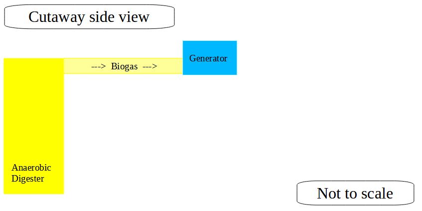
 1. Gas generators can be made to work with biogas.
 2. Sample of Biogas powered generator you can buy.
      1. https://duryeatechnologies.com/mode-biogas-chp-engine-generator-set/
4th Step-Chimney Chamber
1. Hot air enters only at top. Air exhausts only at bottom. Therefore, hottest air is naturally held in the Warming Chamber.
1. Receives exhaust from Generator
2. Receives smoke from Burn Box
2. Contains and warms
1. Warming Tube of Working Air
2. Conduit for unsafe water supply
3. Separate warming tube for generator air intake
5th Step-Warming Tube(s)
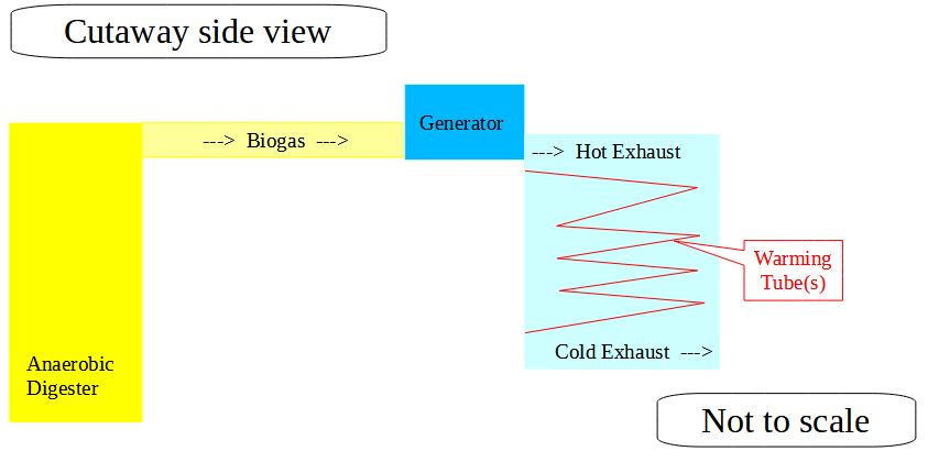
1. Warming Tube (drawn in red)
1. Enters Chimney Chamber near bottom
2. Curls up through Chimney Chamber to direct warmed, dried air into Evaporation Box
2. Warms and dries Working Air which recirculates endlessly
3. A Stirling Engine could be used as the Heat Exchange between the heat source and the Warming Tube, providing free electricity, but reducing the purified water production.
6th Step-Generator Air Intake
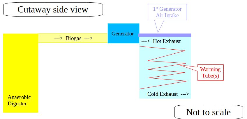
1. Warms combustion air to improve efficiency of the generator
7th Step-Unsafe Water Intake
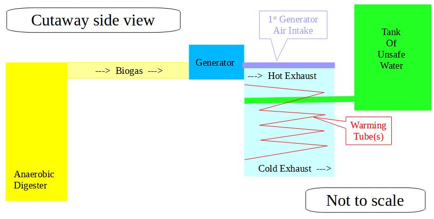
1. Unsafe water to be purified comes from the Tank via a conduit which passes through the Chimney Chamber to be warmed.
8th Step-Evaporation Box
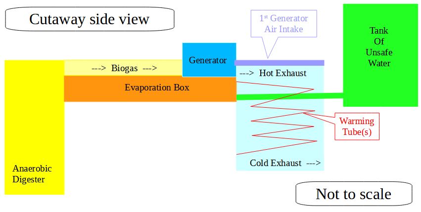
1. Evaporation Box (drawn in orange)
1. 65cm long by 40cm wide by 8cm high gives 5,000cm2 of evaporation space.
2. Sides and bottom of Box are one piece.
3. Top lifts off for easy cleaning.
4. Bottom has drain for easy flushing
2. Receives water from Tank of unsafe water
3. Water is held to 3cm deep by floating valve (not shown)
9th Step-Wicks
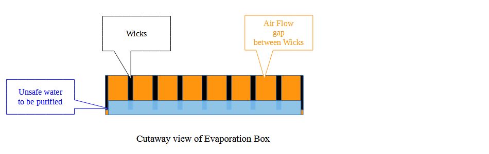
1. Wicks (drawn in black)
1. Stainless steel wool
2. 65cm long by 7cm tall by 1cm wide hang the length of the Box
3. the upper 5cm is the evaporation area; 2cm is in the water and 1cm of water is below the Wicks.
2. Eight air paths between Wicks are 5cm high by 4cm wide
3. The bottoms of the air paths are water surface.
4. One of the 1cm wide Wicks is cut into two 0.5cm wide Wicks and hung at the sides.
1. This creates seven double sided Wicks plus the two single sided Wicks
2. making 16 evaporation surfaces
5. 16 evaporation surfaces of 65cm by 5cm equals 5,200cm2 of evaporation surfaces.
10th Step-Condensing Tube(s)
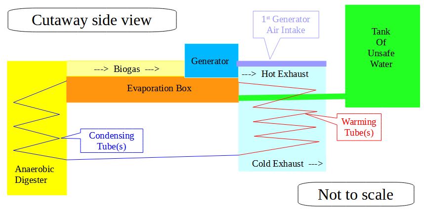
1. Condensing Tube (drawn in blue)
1. Inside Anaerobic-Digester
2. Receives hot, moist Working Air from Evaporation Box
3. Curls down top to bottom within Anaerobic-Digester to facilitate cooling; warms Anaerobic digester
 2. Water condenses as the air is cooled
 3.  Condensing Tube runs through Extraction Chamber to allow extraction of distilled water
 4. Condensing Tube then delivers the cooled, dried Working Air to the Warming Tube to restart the cycle.
11th Step-Extraction Chamber
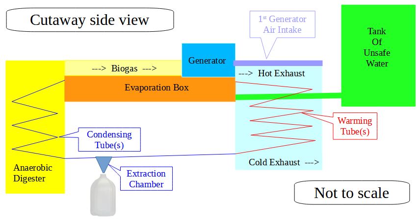
1. Condensed/distilled water drips down from Condensing Tube and is funneled to an attached container
2. Connection to collection container should be sealed since moisture attracts insects
12th Step-Cooling Tube(s)
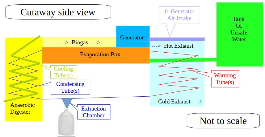
1. (drawn in moss green)
2. When/if anaerobic digester gets too hot, the Cooling Tube removes excess heat
1. Thermal reactive valve at top regulates flow of ambient air
3. Curls up from bottom to top throughout anaerobic digester to facilitate cooling
4. Ambient air enters Cooling Tube at bottom of anaerobic digester and leaves at top
5. best thermophilic (digestion) temp is 50-57ºC
13th Step-Burn Box
1. Thermal reactive valves control ambient air intakes (not shown)
2. To control temperature of exhaust into Chimney Chamber
1. Combustion air is directed to the fuel
2. Completion air is directed to where the smoke leaves the Burn Box
14th Step-Drying Chambers
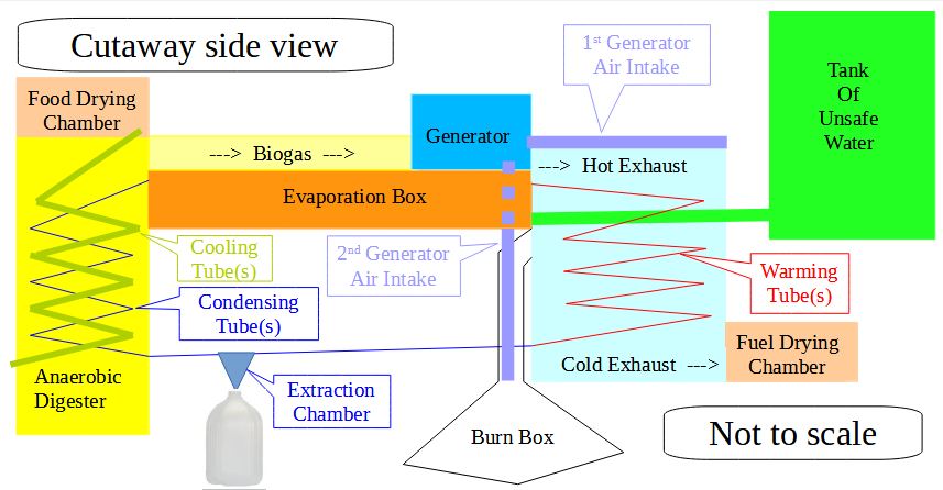
1. The Fuel Drying Chamber is simply a chimney extension where the exhausting air is allowed to pass directly over material to be dried
2. It is perfect for drying fuel to be used the next day
3. The ambient air warmed in the Cooling Tube can be fed directly into the Food Drying Chamber
4. Being fed ambient air, it can be made food safe